66 CIVIL WORKS GUIDELINES FOR MICRO-HYDROPOWER IN NEPAL
4.7 Construction of canals
4.7.1 DESCRIPTION
Once the canal type has been selected and the design carried
out, there are four stages in the actual construction as follows;
setting out of the course of the canal,
preparing the bench for the canal,
excavating the canal, and
lining the canal.
These sections describe a general method of canal
construction and offer examples of other proven methods that
may be suitable under certain conditions.
4.7.2 SETTING OUT
Setting out the canal requires the following equipment and
staff:
Basic equipment:
Level machine (or Dumpy level)
Measuring tape
Tripod
Wooden pegs
Machetes
Mallet
Pick
Hoe
Paint
Paintbrush
Staff:
Surveyor
Chainperson (assistant to surveyor)
Helper to clear vegetation and prepare pegs
The setting out of the canal is done by placing pegs along the
alignment. Depending on the topography, such pegs should
generally be placed at 5 to 20 m intervals along the alignment.
Pegs should also be placed at bends, structures such as drops.
and the beginning and end of crossings and superpassages.
Some intermediate pegs or reference pegs should be placed
just outside the canal alignment using a level machine (or a
Dumpy level). With the use of the level machine, the
difference in levels between these pegs can be calculated.
Such pegs will serve as reference levels for the excavation
work. An alternative to this is to paint marks at exposed rocks
just outside the alignment and calculate their levels.
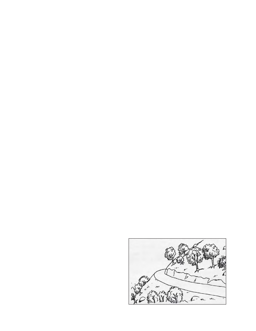
4.7.3 BENCH CUT
The bench of a canal is like a road of uniform width and slope,
see Figure 4.12. The bench is prepared by excavating a strip
of land of even width along the pegs placed earlier on the
canal alignment.
The bench width should be the top width of the canal plus an
allowance for berms on each side of the canal. On the hill
side, a berm of 300 mm is recommended, so that material
washed down by rain from the slope above is not deposited
directly in the canal. A 1.0 m wide berm is recommended on
the outside of the bench, to reduce seepage through the canal
bank, and to provide access for construction and maintenance.
A lesser berm should only be used in conjunction with vertical
cement masonry walls founded on rock. Note that a berm
width less than 500 mm is difficult to walk along.
The slope of the bench should be the same as the slope (S) of
the canal section. Therefore, where there is a change in the
canal slope (in the design) the bench slope should also change
accordingly. The levels of the canal and the bench at different
locations can be verified using a theodolite or a level machine
and the intermediate pegs that were placed outside the canal
alignment earlier.
Once the initial level at the intake is fixed, the subsequent
levels can be calculated based on the slopes. The initial level
can be estimated based on the contour maps of the area or by
an altimeter. Another method is to use the trigonometric
points established by the survey department, but this may
take longer and require more resources. The initial level does
not have to be very accurate (i.e. the exact elevation from the
sea level) but the differences between intermediate pegs
should be accurate, since it is these differences that determine
the slope of the canal.
An example of a level calculation is presented below:
The designer has recommended a slope of 1.5% for a certain
canal section. The topographic map of the area indicates that
the elevation at the intake is around 1600 m above mean sea
level (MSL).
In this case the first peg that is placed at the intake area can
be assumed to be at a level of 1600 m above MSL. If the
second peg is to be placed 20 m (horizontal length)
downstream, the bench level here should be: 20 m x 1.5/100
= 0.30 m down from the intake or 1600 m - 0.30 m
= 1599.70 m above MSL
The subsequent readings between intermediate pegs (i.e.
reference points) can be noted in sequence with similar
calculations.
Figure 4.12 Canal bench